i finished the high voltage power supply
This article borrows from previous ones. In particular, this one goes into detail on the design of this subsystem. I'll summarize briefly:
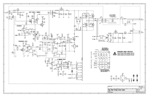
HVPS design

110V from the low voltage supply is used as the main power source. It enters the HVPS and proceeds to an "upside-down" buck converter, which is the point where the output voltage is regulated. This intermediate rail, at about 50 to 60V, is then made into a square wave at 25 kHz by an inverter, which then drives the two transformers in parallel. This design affords maximum flexibility in the transformer design, as they can be separate (one for high voltage, one for filament) and gapless.
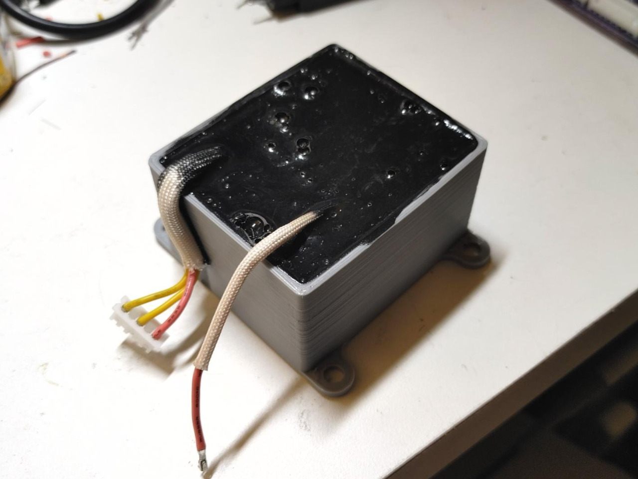
Building the transformer
Back in March, I did the initial HV transformer build. This consisted of a couple 3D-printed bobbins, one with isolation fins, placed onto a square ferrite core and potted in a 3D-printed box:

The bobbins are dipped twice in Glyptal enamel. The transformer is build and placed in the box, with a shim of fishpaper to keep a tight fit. Fiberglass sleeves protect the silicone wires from nicks. Then, the whole thing is potted in MG Chemicals 832TC epoxy potting compound.
Following potting, brass sheet (just basic shit from the hardware store) is formed around it into a shield. This turned out to be necessary — the characteristics of the potted transformer without shielding made the control loop severely unstable for reasons I don't really have a good guess about (before potting, this did not happen). Interestingly, the full potted and shielded assembly results in a significantly more efficient power supply than unpotted, by a factor of about half the idle current.

Testing the system
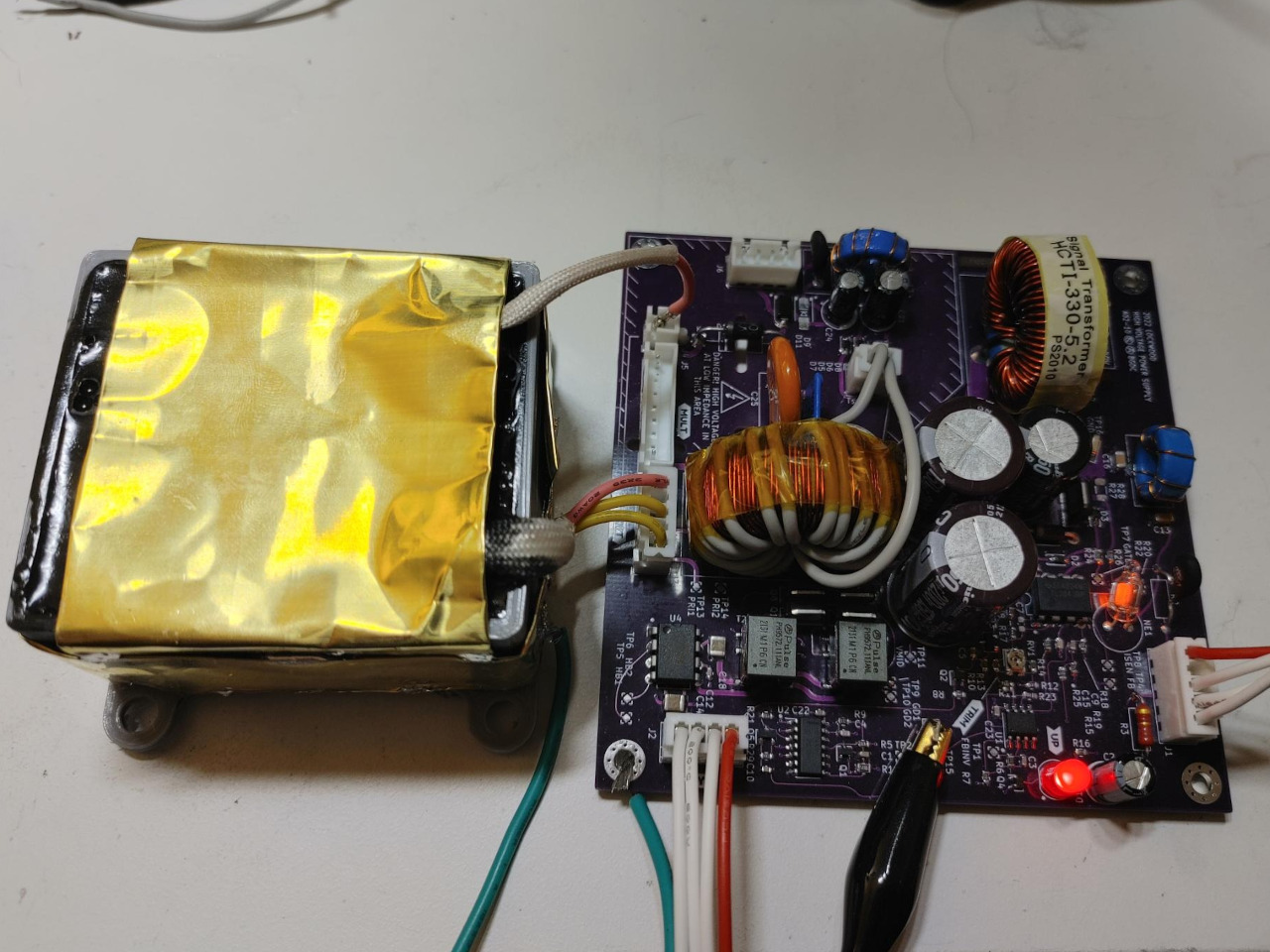
Now that the whole system is together, it needs to be tested again. I built a setup with a separate off-board rectifier for the filament supply (moving it from a -2kV float back up to ground) so the filament supply could be loaded down with a basic e-load — I am not silly enough to try to float an e-load.
Setup not pictured here as I probably wasn't safe enough and don't want to set any bad examples.
Plotting the startup shows it's still more or less stable after the transformer potting. It's slightly underdamped, but I'm not worried about that. The deliberately loose coupling across the HV transformer makes stabilization really tricky, and I am lazy.
Channel 1 (yellow) is the PWM controller compensation node; channel 3 (pink) is the -2kV output:

Injecting a 50kHz reference signal confirms synchronization works as intended:

The system seems a bit less stable without sync, so I'm considering revisiting loop compensation after all. But I don't want to fuck with 2000V on the bench any more than I need to. Maybe if I can get the power stability analysis feature on this Rigol MSO5 working here I'll do a quick writeup on that — cute feature. With sync it's quite stable so I'm not too worried. (Without sync, it runs at a slightly lower frequency.)
Some more pics


Closing thoughts
- Using a power inductor as most of a transformer doesn't really work all that well. It's a distributed gap core and doesn't much care for this mode of operation. It works, but the core loss is high and it gets a bit hot. Not enough to throw out the design, but I don't think I'd do it again.
- I deliberately accepted poor coupling across the HV transformer to make it easier to get excellent isolation. This does present some design challenges. In particular, because the -2kV rail voltage is the variable under regulation, the filament voltage ends up being almost completely unregulated. In my testing I saw it vary from about 7.5V to about 12V under various load conditions. I plan on a simple regulator between this and the actual filament.
- A vacuum pump for the potting compound would have been welcome.
- I wouldn't use gate drive transformers for this again. Good semi-isolated bridge drivers are expensive on Digi-Key, but I've since found a pretty dope part on LCSC that doesn't cost a fortune.
Design files are here
Last modified: Wed Jun 8 20:49:32 MDT 2022.
Converted from blog/20220608-hvps.md.
RSS feed — Blog —
Home — Up — Index